MIL-DTL-24784 / 21B (SH)
accordance with MIL-DTL-24784 (see 6.2).
3.3.1 Type style and sizes. Type style and sizes shall be comparable to those shown in
MIL-DTL-24784 except for the styles and sizes listed in table I.
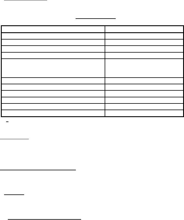
TABLE I. Text size and style. (note 1)
USE
SIZE AND STYLE
Art callouts (pictorials, and so forth)
8 point
Art lettering
7 point
Circled keying numbers on FBD art
8 point
Circled keying numbers on pictorials
10 point
8 point
Art drawing sheet numbers, title blocks, main
drawing number blocks, hardware boundary
titles, and functional boundary titles
Running heads
10 point bold
Dangers
14 point bold
Warnings (heading)
14 point bold caps, boxed
Cautions (heading)
14 point bold caps, underlined
Notes (heading)
10 point caps
Rules
1 point
1 Text for notes, dangers, cautions, and warnings shall be short-measured; that is indented from
left and right margins of overall text area.
3.4 Arrangement. Unless otherwise specified in the TMCR (see 6.2), the manual shall be
arranged in a standardized format [that is, front matter, technical content, appendices, glossaries,
indices and Technical Manual Deficiency/Evaluation report (TMDER)] and appropriately divided
by volume, part, chapter and section in accordance with the requirements of MIL-DTL-24784.
3.5 Format and preparation instructions. Unless otherwise specified in the TMCR, the writing
style, safety precautions, tabular material, and numbering shall be in accordance with
MIL-DTL-24784 and as follows (see 6.2).
3.5.1 Graphics. Unless otherwise specified in the TMCR, the preparation of illustrations,
drawings, diagrams and sketches shall be in accordance with the requirements of
MIL-DTL-24784 and the following (see 6.2).
3.5.1.1 Functional block diagrams (FBDs). A system of FBDs shall be used to depict the
functional divisions of the equipment. (A functional division is defined as a function or a portion
of a function that performs a particular task in relationship to the entire equipment.) The
diagrams shall depict the equipment in an integrated manner; that is, a master FBD shall show
each function of the equipment; primary FBDs shall show the functional divisions of the
equipment; and third-level or lower-level FBDs shall show further functional subdivisions of
complex subfunctions. The lowest level of FBD shall be directly linked to functional circuit
diagrams (FCDs) contained in Chapter 5 or to the hardware where the function is performed.
4
For Parts Inquires call Parts Hangar, Inc (727) 493-0744
© Copyright 2015 Integrated Publishing, Inc.
A Service Disabled Veteran Owned Small Business