MIL-DTL-83495C (USAF)
a. Additional information to be recorded to complete the analysis.
b. Unusual conditions causing fault recognition and isolation.
c. Minor coniguration differences.
3.5.5.2.4.3 Operating limits. Operating limits shall be given, where possible, the words "normal" or
"OK/Not OK," and nominal values shall be given, as required.
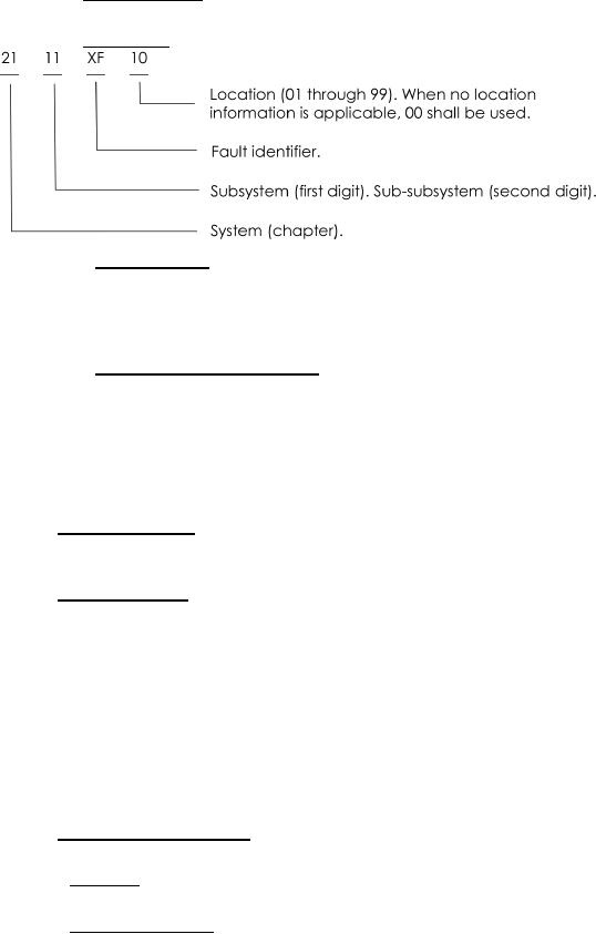
3.5.5.2.4.4 Fault codes. The code shall be 8 digits, alphanumeric as follows:
3.5.5.2.4.4.1 Alpha identiier. A two-letter alpha identiier shall be assigned so that the initial letter is the
same for a basic fault and each of its related subfaults. The letters "A," "B," and "C" shall be reserved for
exclusive use as the second letter for a basic fault. The letters "X," "Y," and "Z" shall be reserved for
exclusive use as the irst letter for a single entry fault. The letters "OO" shall be used for faults not
listed. The letter "I" (eye) shall not be used.
3.5.5.2.4.4.2 Subsystem and sub-subsystems. The third and fourth digit shall follow MIL-STD-1808. To
prevent duplication, if interfacing between two or more sub or sub-subsystems, information shall be combined
under one subsystem number. Cross-referencing shall be shown in either the pictorial alphabetical table of
contents or in the fault reporting material. In addition, the following requirements shall apply:
a. When fault reporting material is revised, the alpha fault designators may be extended or canceled,
but once canceled may not be reused for another fault.
b. It is not essential for the fault designators to appear in alphabetical order.
3.5.5.3 Log book reports . When speciied (see 6.2t.), the FI manual shall duplicate the log book reports
contained in the FR manual. The FR manual shall contain complete word descriptions of all coded faults.
The reports shall appear at the end of the system/subsystem fault reporting information. (see igures 8 and 9 )
3.5.5.4 Location of parts. Parts shall be illustrated in fault isolation procedures and shall be shown
relative to known equipment features (see igure 11). Parts shown on related schematics which are not
called out in the fault isolation procedure shall:
a. Not be required where location is obvious or becomes obvious as a result of gaining access
b. Be shown in the primary subsystem. A reference shall be provided if required.
c. Provide location information, not exceed two s for each subsystem.
d. Be illustrated as line drawings. Several illustrations shall be included on a provided clarity is
maintained.
e. List all related CBs or fuses for a particular sub or sub-subsystem at the beginning of the parts
location information. CB number, name and location shall be shown.
3.5.5.5 Fault isolation information. The FI manual shall contain fault isolation (troubleshooting) procedures
which immediately follow the parts location information (see igure10
3.5.5.5.1 Sequence. Isolation procedures shall be provided for each coded fault in alphabetical sequence
(except as in 3.5.5.2.4.4.2). One isolation procedure shall be used for several coded faults, when applicable.
3.5.5.5.2 Fault code location. The fault code shall appear in the left cell of the chart. The irst code
shall be in the upper left corner. Where the isolation procedure applies to more than one code, all
codes shall be shown.
20
For Parts Inquires call Parts Hangar, Inc (727) 493-0744
© Copyright 2015 Integrated Publishing, Inc.
A Service Disabled Veteran Owned Small Business